F100-L Microprocessor Architecture
The Ferranti F100-L is a single-address, single accumulator, 16-bit word length microprocessor with 2’s complement fixed-point arithmetic.
The processor has 29 basic instructions, which can be subdivided into six main categories:
arithmetic and logical,
shifts,
bit tests and jumps,
link stack (for interrupt handling),
double-length (32-bit) instructions, and
external functions
The last of these categories, external functions, is a notable feature. The F100-L brings out enough of the internal control bus to pins so that instructions which are not fully decoded inside the CPU can be passed out to a co-processor for further decoding and execution.
The processor provides 4 main addressing modes for most instructions: direct, pointer indirect, immediate data and immediate indirect. Direct and pointer direct encode the operand in with the single 16 bit opcode for optimal efficiency. Additionally most instructions implementing pointer access are able to select pre-incrementing or post decrementing of the pointer in the same instruction.
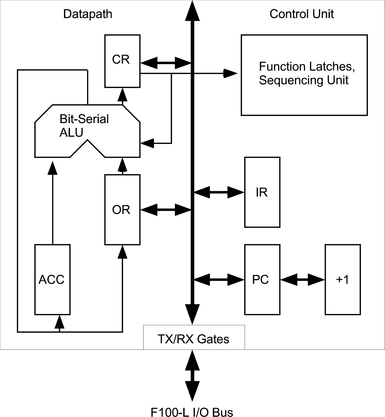
Datapath Registers and Function Unit
The datapath side of the machine has only 3 registers
the 16-bit accumulator (ACC)
the 16-bit operand register (OR)
the 7-bit condition register (CR)
All arithmetic and logical operations are performed on one or more of these registers. Any instructions specifying a memory location as an operand will access that memory location and store the result in the operand register before processing. Once all operands are in place the function unit will perform the required operation and save the result either to the accumulator, or first to the OR and then to memory if a memory location is the final destination.
Although the OR is usually a very transitory point, it is possible to access and set the contents of this register directly by using one of the double-word shift instructions.
The function unit itself is a bit-serial unit. All operations are processed one bit at a time, and every instruction requires at least 18 logic cycles in addition to any memory accesses.
Control Unit
The Control Unit has two main registers
the 15-bit Program Counter (PC)
the 16-bit Instruction Register (IR)
The PC holds the address of the next instruction, or operand to be fetched from memory. It has a built-in incrementing unit and can be loaded directly from the main system bus during jump and call instructions.
The IR serves a dual purpose as it can hold either instructions or addresses. The IR is loaded with an instruction during the instruction fetch. If the IR is subsequently required to hold an address, then any instruction bits which need to be preserved are transferred into ‘Function Latches’ elsewhere in the control block.
The Condition Register
The Condition Register hold 7 flag bits.
Bit
Flag
Reset State
Name
Function
0
I
0
Interrupt Disable
disables interrupts when set
1
Z
X
Zero
indicates zero results
2
V
X
Overflow
indicates overflow in arithmetic and shift operations
3
N
X
Negative sign
indicates sign of results
4
C
X
Carry
carry bit, set at the end of arithmetic and shift operations
5
M
0
Multi-Length
enables use of the carry bit as input to arithmetic and shift operations
6
F
0
Fail
set if an external function , DMA or IO cycle does not complete within an externally defined time.
The ‘M’ flag is cleared by a CPU reset, interrupt or execution of the CAL (Call subroutine) instruction. It can also be cleared or set explicitly by the user through one of the bit set or clear, rotate or shift instructions.
Memory Space
The program counter and addressing logic are only 15 rather than 16-bits wide, so the maximum addressable memory size is 64 KBytes, arranged as 32K by 16-bit words. Limiting the addressable memory to 32K rather than 64K words seems like an odd choice in hindsight, since a full 16 bit implementation would have doubled the address space at almost no extra cost in internal logic. However, in 1975 memory was not plentiful and Ferranti was selling micro-computer systems with the F100-L a few years later starting with just 4KBytes of RAM. The successor chip, the F200-L, introduced in 1984 added the additional address bit and so is able to address 64Kwords even without the additional memory management unit (MMU) companion chip launched at the same time.
In this address space, the lower portion of the address range is treated differently to the rest of the range.
The first 256 words of memory can be used as pointers for Pointer Indirect Addressing modes, with pre-increment and post-decrementing available for the pointers themselves. Locations 1-255 are available for user programs; location 0 is reserved for use as the processor’s link stack pointer since the CPU has no internal stack pointer state of its own. The various jump to and return from subroutines will always adjust the value of the stack pointer in location 0 appropriately.
Additionally when using any kind of indirection, the instruction word is able to encode up to 11 bits of address in a single word opcode (Direct addressing). Therefore it is preferred to use memory locations up to 0x07FF as data or additional pointers.
Memory above 0x0800 can be used for additional bulk data or program instruction code.
Memory Area
Primary Usage
0x0000
Link Stack Pointer
0x0001 - 0x00FF
Pointer area
0x0100 - 0x07FF
Directly addressed Data or Program Area
0x0800 - 0x7FFF
Data or Program Area
Note: The user must always initialise the link stack pointer with an ODD value. The return from stack operations assume that the top of the stack is odd and access this location and the one immediately below by simply zeroing the LSB when popping off the condition register and return address contents.
Processor Start Up
When the processor is reset, program execution begins at one of two addresses selected by the state of the AdSel pin (both of which are above the Direct address mode area - see above).
AdSel Pin
Program Counter Initial State
0
0x4000
1 (or floating)
0x0800
Addressing Modes
The F100-L CPU supports 4 addressing modes and these are described below together with the assembler syntax.
Direct addressing
The address of the operand data is encoded in an 11 bit field in the opcode word. In the assembler this mode is denoted by providing just a bare operand. e.g.
AND 0x444 ; A <- A & (0x444)
If an operand is used which is larger than 11 bits, the assembler will emit a warning and instead assemble the instruction using the Immediate Indirect Addressing mode below. This will always achieve the correct behaviour, but the latter mode requires two instruction words where Direct Addressing, with a smaller operand, needs only one.
Immediate addressing
The 16 bit operand data is placed in the word immediately following the opcode. In the assembler this mode is denoted by a comma (,) immediately before the operand e.g.
AND ,0x4444 ; A <- A & 0x4444
Pointer Addressing
The address of the operand data is encoded in an 8 bit field in the opcode word. Optionally the value of this pointer can be pre-incremented or post-decremented. This mode is denoted in the assembler by a slash (/) immediately in front of the operand and optionally a plus (+) or minus (-) symbol following. e.g.
AND /0x44  ;  A <- A & (0x44)
AND /0x44+ ;  (0x44) <- (0x44) + 1 ; A <- A & (0x44)
AND /0x44- ;  A <- A & (0x44) ; (0x44) <- (0x44) -1
Immediate Indirect Addressing - Double Word Operations
The 15 bit address of the operand data is placed in the word immediately following the opcode. This mode is denoted in the assembler by a dot (.) immediately in front of the operand, e.g.
AND .0x4444 ; A <- A & (0x4444)
Behaviour is slightly different for jump instructions where the provided operand will be used as the jump address, e.g.
JMP .0x4444 ; PC <- 0x4444
Immediate Indirect Addressing - Three Word Operations
Bit Conditional jump operations can use another variation of this addressing mode, where a jump is conditional on the value of a bit in a memory location, so that two operand words are needed, one for the memory location to be inspected and a second for the jump destination. e.g.
JBS 0x2 0x4444 0x5555 ; PC <- 0x5555 if (0x4444)[4]==1 else PC+1